Klipper Expander
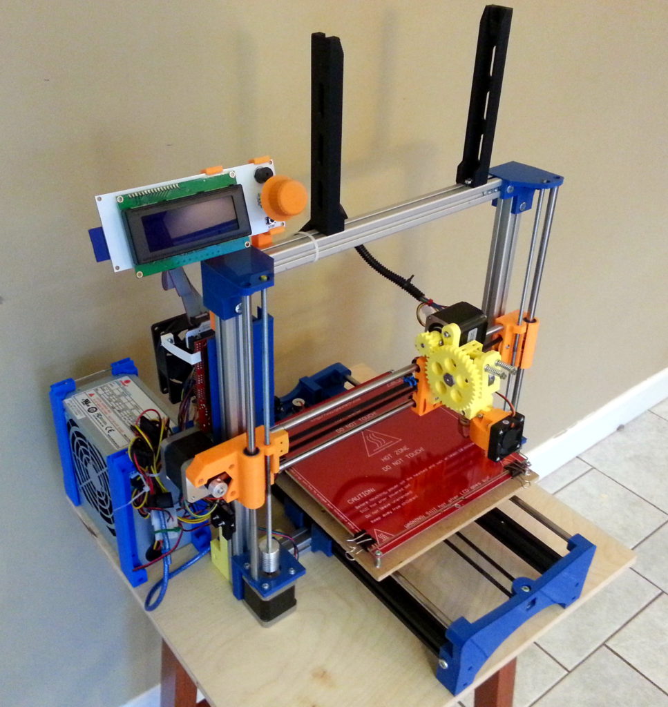
After building a few 3D printers I realized how nice it would be to have a control board for just some heaters or lights with some temperatures sensors and GPIO pins. After tinkering in KiCad for a bit on some other projects (Nano Display Adapter and a flat-flex display breakout), I realized that this could be a viable project.
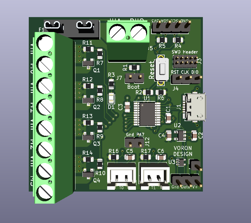
Looking around and talking with other users in the VORON CoreXY 3D printer discord I settled on 4 Mosfet outputs, 2 thermistor inputs, I2C header, 1 level-shifted NeoPixel output and an SWD header for easy debugging. The STM32F042F6P6 was selected as it was already known to work with the Klipper 3D printing firmware as well as having enough memory for the project in addition to having a direct USB connection so no USB to UART chip was needed.. Micro USB was chosen for its availability and
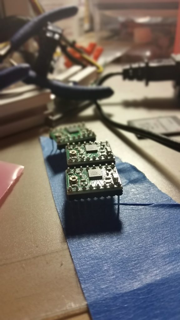
The initial design was to be a squarish board with the 4 mosfet outputs on the left side with the USB and SWD headers on the right. 20-TSSOP package was picked as it allowed for the easiest assembly by hand as this board is intended to be easily manufacturer by hand without needing a hot air station or reflow oven. All resistors, capacitors and LED’s are to be 0805 or larger with other components selected for availability on JLCPCB’s SMD assembly tool and Digikey/Mouser. The board uses a mini-blade fuse that is common on the SKR series of control boards and allows for easy replacement should the need arise.
After looking at the layout for the Expander and discussing with a few other people, we decided that it would make more sens to have the board transition to more of a thin rectangle shape to allow for most of the outputs to be on one face making mounting and wire routing in a printer easier.
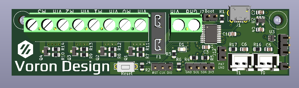
The final design layout has moved to a 100mm x 25mm PCB with mounting holes spaced 92mm apart (4mm in from each corner). This allowed for much easier routing as the Vin and all mosfet outputs come out the top as well as the USB Micro-B connector. The board was sent to JLCPCB to have boards made and SMD assembled with the BOM and Centroid files generated from KiCad.
The first run came back and as JLC doesn’t assemble through hole parts or the USB connected (doesn’t have any in stock). after a bit of careful hand soldering and checking with a multi meter I had the USB connector soldered in. Now, at this point I realized that i REALLY hadn’t figured out the software/flashing side of things. Fortunately, another member of the group had ordered some boards and with his help I was able to see the device on the Raspberry Pi thought lsusb as STM Device in DFU Mode. The board was also detected through dfu-util --list as device ID 0483:df11
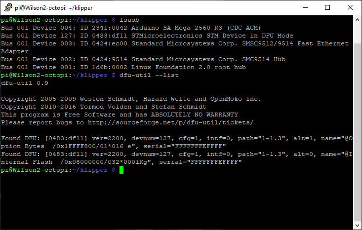
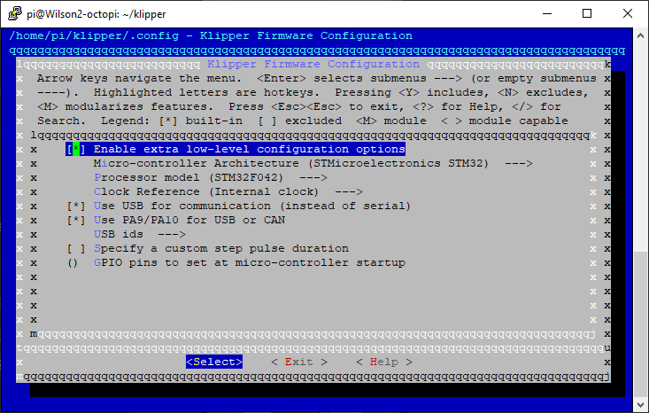
Setting klippers make menuconfig options and running the make command returned no error and i was able to flash the device by specifying its ID as the FLASH_DEVICE parameter.
The board had the klipper firmware on it and now was detected with it’s own unique ID from the STM32 chips serial number. /dev/serial/by-id/usb-Klipper_stm32f042x6_050028000E43504735393520-if00
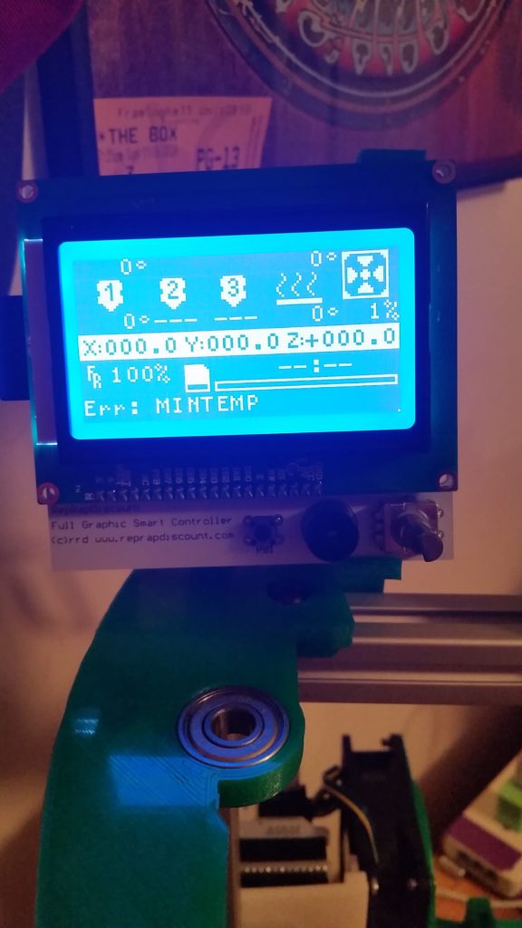
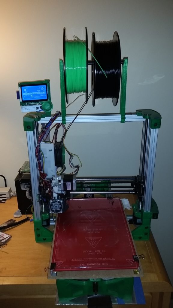
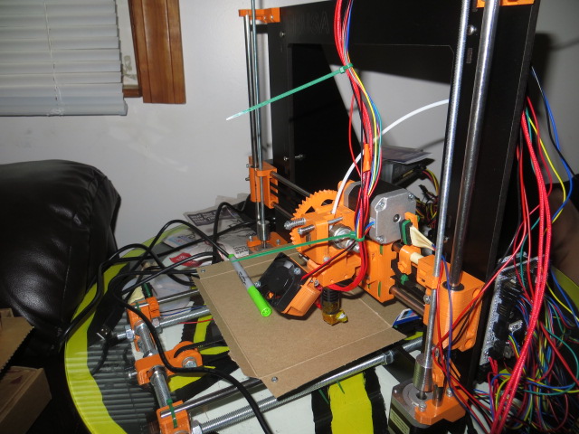
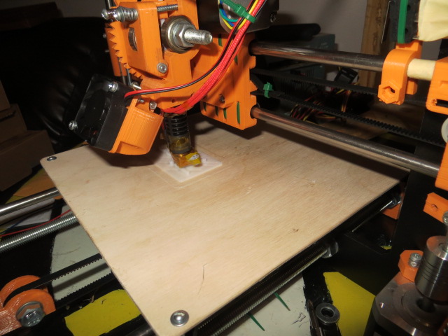
The board has been installed in my V2 for a few months no with no issues. It currently controls my case lighting, exhaust fan as well as a chamber thermistor. I plan on adding some NeoPixels to the V2 at some point and will use the expander to control them.